ClimateSync Centre

Configuration

Manuals & Tools

User’s ClimateSync Configuration Tool: native Windows desktop app. Communicates with ClimateSync hardware via USB-C virtual COM ports and raw TCP/IP (custom handshake, port 10102) using a custom ASCIl command set; supports discovery/ identification and persistent connections.

Features engineering-friendly Ul, CSV import/export, logging, real-time monitoring/diagnostics; targets Windows 10/11; distributed as versioned Windows executable.

Hysteresis Configuration

ClimateSync Hysteresis Configuration

Understanding ClimateSync Hysteresis

Hysteresis Infographic

ClimateSync Hysteresis

Automation Heat Command Target

Automation Heat Command Target
Configuration

Automation Heat Command Target
Explained

Automation Heat Command Target
Infographic

Automation Heat Command Target
Installer Guide

Boiler Delay Time

Boiler Delay Time
Configuration

Boiler Delay Time
Explained

Boiler Delay Time
Infographic

ClimateSync Boiler Delay Time
Configuration Guide

ClimateSync Auto Mode (v)

ClimateSync Auto Mode
Configuration

ClimateSync Auto Mode
Explained

ClimateSync Auto Mode
Infographic

ClimateSync Auto Mode
Configuration Guide

ClimateSync Auto Mode
Configuration Guide

Installation Engineer Manual

This guide explains how to configure ClimateSync Auto Mode using the ClimateSync Configuration Tool.

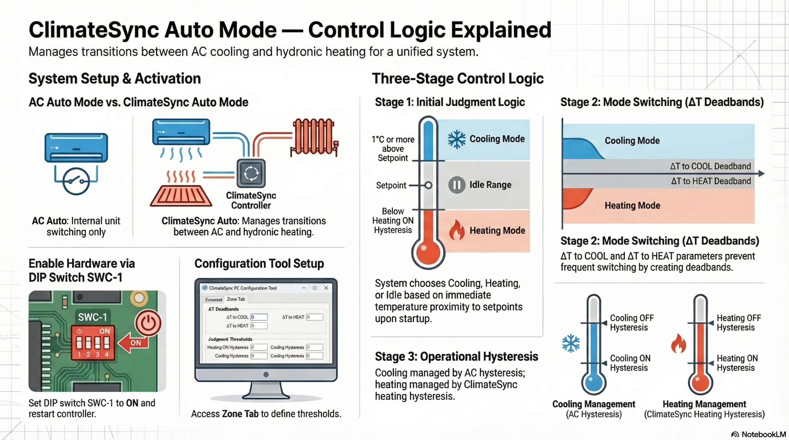
ClimateSync Auto Mode allows the controller to automatically select between cooling and hydronic heating based on the room temperature relative to the setpoint.

  1. Understanding the Two Types of Auto Mode

Before configuring the system, installers must understand the difference between the two Auto modes available in a ClimateSync system.

1.1 AC Auto Mode

AC Auto Mode is controlled entirely by the air-conditioning system.

In this mode the AC unit automatically switches between:

  • AC Cooling
  • AC Heating

ClimateSync does not control the heating technology in this mode.

This mode is normally used when both heating and cooling are provided by the air-conditioning system.

1.2 ClimateSync Auto Mode

ClimateSync Auto Mode is controlled by the ClimateSync controller.

In this mode the system operates using:

  • AC Cooling
  • Underfloor Heating
  • Radiator Heating (if configured)

Instead of switching between AC cooling and AC heating, ClimateSync switches between:

Cooling → Air-conditioning system
Heating → Hydronic heating (UFH or radiators)

This configuration is typically used when:

  • Cooling is provided by AC units
  • Heating is provided by underfloor heating or radiators
  1. Enabling ClimateSync Auto Mode

ClimateSync Auto Mode must first be enabled on the controller hardware.

Step 1 – Locate DIP Switch SWC-1

On the ClimateSync controller PCB, locate the DIP switch block SWC.

Step 2 – Set DIP Switch SWC-1 to ON

Set:

SWC-1 = ON

This enables ClimateSync Auto Mode functionality.

Step 3 – Restart the Controller

After changing the DIP switch setting:

  1. Power cycle the ClimateSync controller
  2. Allow the system to reboot fully

After restart, ClimateSync Auto Mode will become available in the Configuration Tool.

  1. Opening the ClimateSync Configuration Tool
  1. Connect the computer to the ClimateSync controller
  2. Launch the ClimateSync Configuration Tool
  3. Establish communication with the controller
  4. Navigate to the Zone Tab

Each zone has its own configuration section.

  1. ClimateSync Auto Mode Settings

Within each Zone Tab, locate the section titled:

ClimateSync Auto Mode

The following parameters will be visible:

  • ClimateSync Auto Mode State
  • ΔT to COOL (Changeover Deadband)
  • ΔT to HEAT (Changeover Deadband)
  • Judgment to Heat below ON hysteresis

These parameters determine how the controller selects heating or cooling operation.

  1. Initial Auto Mode Judgment

When either a zone is:

  • Switched ON in Auto mode
  • Changed from another mode into Auto mode

ClimateSync must decide whether to start in:

  • Cooling Mode
  • Heating Mode
  • Idle

The controller performs an initial judgment instead of waiting for the ΔT thresholds.

5.1 Cooling Judgment

If the room temperature is:

1°C or more above the setpoint

ClimateSync will immediately start the zone in:

Cooling Mode

Once cooling mode has started, the zone will remain in cooling mode until the ΔT to HEAT threshold is reached.

5.2 Heating Judgment

If the temperature is sufficiently below the heating threshold, the system will start in:

Heating Mode

The exact point at which heating starts is determined by the parameter:

Judgment to Heat below ON hysteresis

Example:

If the value is set to 0.1°C, heating will start when the room temperature drops 0.1°C below the heating ON hysteresis threshold.

5.3 Idle Range

If the room temperature is between the cooling judgment threshold and the heating judgment threshold:

The system will remain Idle.

The controller will wait until either:

  • The cooling threshold is reached
    or
  • The heating threshold is reached

before activating the system.

  1. Mode Switching Logic

Once the initial mode has been selected, the ΔT parameters control when the system switches between heating and cooling modes.

6.1 ΔT to COOL (Changeover Deadband)

This parameter defines when the system switches from Heating Mode to Cooling Mode.

Example:

Setpoint = 23°C
ΔT to COOL = 3°C

Cooling mode will be activated when the room temperature reaches:

26°C

6.2 ΔT to HEAT (Changeover Deadband)

This parameter defines when the system switches from Cooling Mode to Heating Mode.

The ΔT values create a deadband around the setpoint, preventing frequent switching between heating and cooling.

  1. On/Off Operation

It is important to understand that the ΔT parameters only control mode switching.

They do not control when the system turns on or off.

7.1 Cooling Operation

Once the system is in Cooling Mode, the ON/OFF operation is controlled by:

The air-conditioning system hysteresis

The AC unit decides when to start and stop cooling.

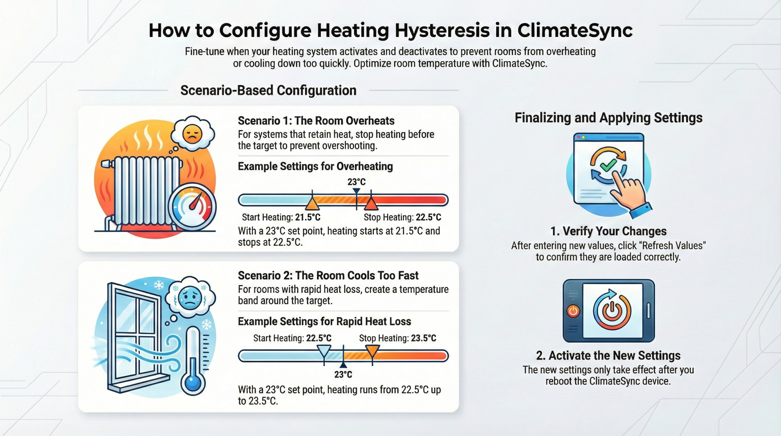
7.2 Heating Operation

Once the system is in Heating Mode, the ON/OFF operation is controlled by:

ClimateSync heating hysteresis

This hysteresis determines when the underfloor heating or radiators are activated.

  1. Per-Zone Configuration

All Auto Mode parameters are configured individually for each zone.

Each zone may require different values depending on:

  • Room size
  • Thermal response of the floor
  • Comfort requirements
  • Radiator vs underfloor heating system

Adjust parameters accordingly for each zone.

  1. Example Configuration

Example system configuration:

Setpoint: 23°C

Room Temp: 23°C

Parameters:

ΔT to COOL = 3°C
ΔT to HEAT = 3°C
Judgment to Heat below ON hysteresis = 0.1°C

System behaviour:

  • Change to Cooling begins at 26°C
  • Heating begins when temperature drops below the heating threshold
  • Idle range exists between the heating and cooling thresholds

This configuration ensures stable operation without rapid switching.

  1. Summary

ClimateSync Auto Mode operates in three stages:

  1. Initial Judgment

Determines whether the zone starts in:

Cooling
Heating
or Idle

  1. Mode Switching

Controlled by:

ΔT to COOL
ΔT to HEAT

  1. Operational Control

Cooling ON/OFF → controlled by AC system
Heating ON/OFF → controlled by ClimateSync heating hysteresis

ClimateSync Boiler Delay Time
Configuration Guide

Installation Engineer Manual

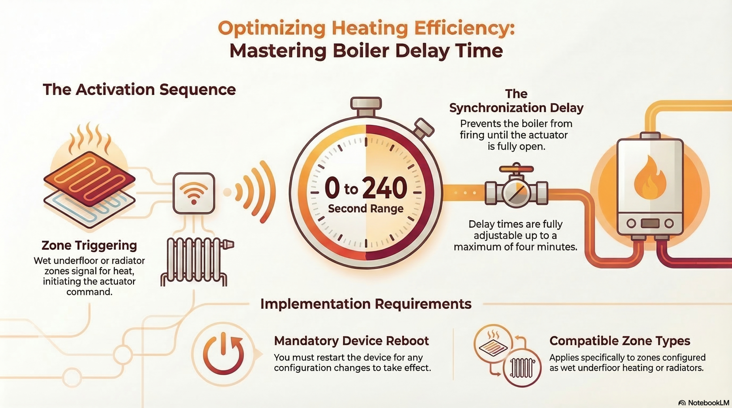
This guide explains how to configure the Boiler Delay Time parameter in a ClimateSync system using the ClimateSync Configuration Tool.

The Boiler Delay function is used to protect the boiler and improve system stability by delaying the boiler activation when heating demand begins.

  1. Purpose of the Boiler Delay Time

In hydronic heating systems, such as underfloor heating or radiator systems, it is often undesirable for the boiler to start immediately when a heating zone requests heat.

The Boiler Delay Time allows the system to wait for a defined period before activating the boiler.

This provides several advantages:

  • Prevents unnecessary boiler starts for short heating demands
  • Allows valves and pumps to stabilise before heat generation begins
  • Reduces boiler cycling
  • Improves overall system efficiency
  1. When Boiler Delay Time is Used

The Boiler Delay function is active when the ClimateSync system controls:

  • Underfloor heating
  • Radiator heating
  • Any hydronic heating system connected to the boiler relay output

The delay is applied when:

  • A zone calls for heating
  • The system transitions into heating mode
  • The heating demand signal is sent to the boiler

Instead of immediately activating the boiler, the system waits for the configured delay time.

  1. Accessing the Boiler Delay Configuration

The Boiler Delay Time is configured using the ClimateSync Configuration Tool.

Step 1 – Connect to the Controller

  1. Connect the computer to the ClimateSync controller
  2. Launch the ClimateSync Configuration Tool
  3. Establish communication with the device

Step 2 – Navigate to the Common Settings

  1. Open the Common Tab

Locate the Boiler Delay Time section .

Within this section you will find the setting:

  1. Configuring the Boiler Delay Time

The Boiler Delay Time defines how long ClimateSync waits before sending the command to start the boiler.

Configuration Steps

  1. Open the Common Tab
  2. Locate Boiler Delay Time
  3. Enter the desired delay value
  4. Save the configuration to the controller

The value is typically defined in seconds (0-240).

  1. How the Boiler Delay Works

When a heating zone requests heat, the following sequence occurs:

  1. A zone requires heating
  2. ClimateSync activates the zone heating Relay (UFH valve or radiator)
  3. The Boiler Delay Timer starts
  4. When the timer expires, the boiler output relay is activated

This ensures that the heating circuit is ready before the boiler begins producing heat.

  1. Typical Boiler Delay Settings

Recommended values may vary depending on system design.

Typical delay values include:

System Type

Typical Delay

Small radiator systems

30–60 seconds

Underfloor heating systems

60–180 seconds

Large multi-zone systems

2–5 minutes

These values help prevent unnecessary boiler cycling.

  1. Example Operation

Example configuration:

Boiler Delay Time = 120 seconds

Sequence:

  1. Zone calls for heating
  2. ClimateSync opens the underfloor heating valve
  3. The delay timer begins
  4. After 120 seconds, the boiler output is activated

The boiler will now begin heating the system.

  1. Multiple Zone Heating Requests

If multiple zones request heating:

  • The boiler delay is triggered by the first heating demand
  • Additional zones joining during the delay period do not reset the timer

This ensures stable system operation.

  1. Important Installation Notes

Installation engineers should ensure:

  • The boiler control relay is wired correctly
  • The delay time matches the hydraulic response of the system
  • Pump and valve activation occurs before boiler firing

Improper delay configuration may cause:

  • Boiler short cycling
  • Reduced system efficiency
  1. Verification After Configuration

After configuring the boiler delay time:

  1. Activate a heating zone
  2. Observe the heating valve opening
  3. Verify that the boiler activation occurs after the configured delay

Confirm that system operation matches the intended sequence.

  1. Summary

The Boiler Delay Time ensures that:

  • Heating circuits stabilise before boiler activation
  • Boiler cycling is reduced
  • System efficiency and reliability are improved

Correct configuration of this parameter is essential for stable hydronic heating operation.


Automation HEAT command Target
Installer Guide

Key Concept

ClimateSync Heating Modes:

  • AC Heat (“heat” mode) – Heating provided by the air-conditioning system.
  • Floor Radiant Heat (“haux” mode) – Heating provided by underfloor heating or radiators.
  • Combined Heat (“hh” mode) – Both radiant heat and AC heat operate together.

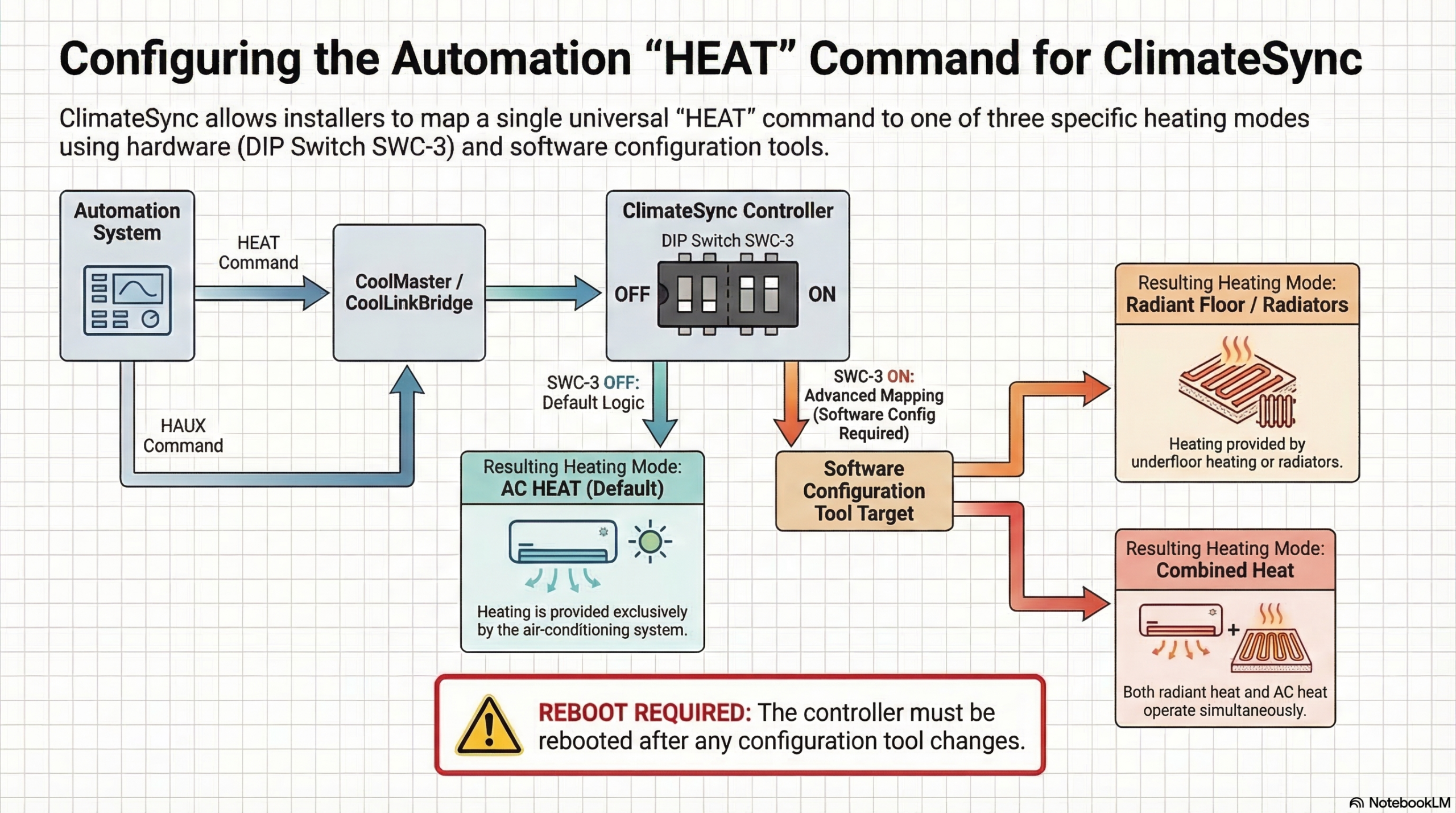
Automation systems sometimes only have one heat command (“HEAT”).
ClimateSync supports three different heating modes, and installers must understand which one will be triggered.

Default Behaviour

By default, when an Automation system sends a HEAT command via CoolMaster / CoolLinkBridge, ClimateSync triggers:

AC HEAT mode

DIP Switch Behaviour

When DIP Switch SWC-3 = OFF

  • HEAT command → AC HEAT
  • HAUX command → Radiant heating (UFH or radiators)

Note:
Whether the radiant heating is underfloor heating or radiator depends on zone configuration settings, which are explained separately.

When DIP Switch SWC-3 = ON

The system behaviour changes:

  • HEAT command replaces HAUX
  • The HEAT command now controls radiant heating

At this point the installer can configure what the HEAT command should do.

Configuration Tool Setting

Using the ClimateSync Configuration Tool:

Go to:

Common Tab → Automation Heat Command Target

A dropdown allows the installer to select:

1️⃣ Radiant Heat / Radiator
→ HEAT command activates UFH or radiator heating

2️⃣ Combined Heat (HH Mode)
→ HEAT command activates both radiant heating and AC heating together

Important Step

After changing this configuration:

⚠️ The ClimateSync controller must be rebooted for the new setting to take effect.

ClimateSync Hysteresis
ClimateSync configuration tool to manage on/off hysteresis for various heating systems, such as wet or electric floor heating, radiators, and trench heaters.

Introduction to On/Off Hysteresis

The on/off hysteresis feature allows you to control exactly when heating activates and deactivates in relation to a specific set point. This is a zone-by-zone setting, meaning you can customize the behavior for every individual room or area controlled by a ClimateSync relay.

How it Works: The Basic Setup

By adjusting the “on” and “off” settings, you define the temperature range for heating:

  • On-Hysteresis: Determines how many degrees below the set point the heating kicks in.
  • Off-Hysteresis: Determines at what temperature the heating stops.
  • Example: If the set point is 23°C, setting the “on” hysteresis to 1° below and “off” to 0° means the heat starts at 22°C and stops exactly at 23°C.

Advanced Scenarios and Customization

The tool allows for specific adjustments based on the unique thermal properties of a site:

  • Preventing Overheating: In some locations, underfloor water is kept at very high temperatures. Even after the valve closes, the floor continues to emit heat, causing the room to overshoot the set point. To solve this, you can set the off-hysteresis to a negative value (e.g., -0.5°). This stops the heating early (at 22.5° for a 23° set point), allowing the residual heat in the floor to bring the room naturally to the desired temperature.
  • Managing Rapid Heat Loss: If a building loses heat quickly, you may want a more balanced approach. In this case, you can set the heating to stop half a degree above the set point and start half a degree below. This ensures the room stays warmer for longer to compensate for the fast cooling.

Finalizing and Applying Settings

To ensure your configuration is successful, follow these two critical steps:
  1. Refresh Values: After making changes, click “refresh values” and allow a minute for the system to load. This allows you to verify that all settings are exactly as you intended.
  2. Reboot the Device: Settings will not take effect in actual operation until the ClimateSync device is rebooted. You can do this by:
    • Manually cycling the power to the device.
    • Using the “reboot and reload” option within the terminal.

Once the reboot is complete, you can review the settings across different zones one last time to ensure everything is correct.  
This website uses cookies to ensure you get the best experience on our website.
If you continue to use this website, you consent to our use of cookies.